Concept
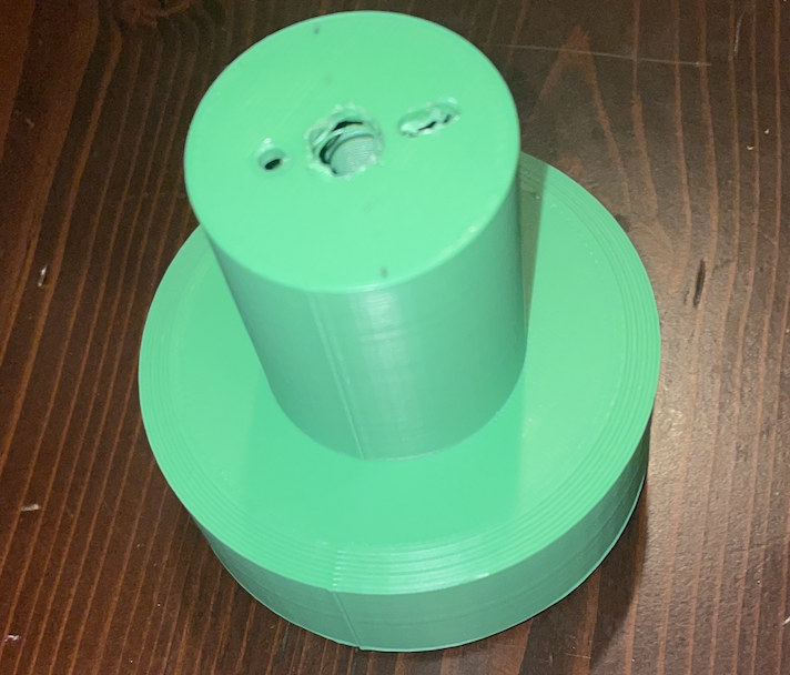
To start off, I created a simplistic design, consisting of a base, and an arm. The base would contain the motor, while the arm would contain the candy. A servo hole was created in the arm but was not used
The design was created in tinkercad and was printed in green PLA @ 20% infill
And yes, I did hand drill the holes since I forgot to cad them in
Materials
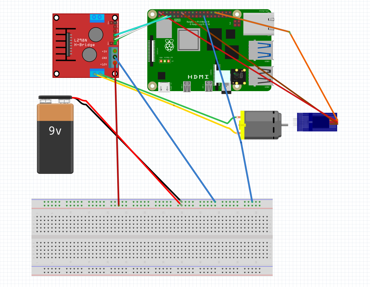
- Power Supply
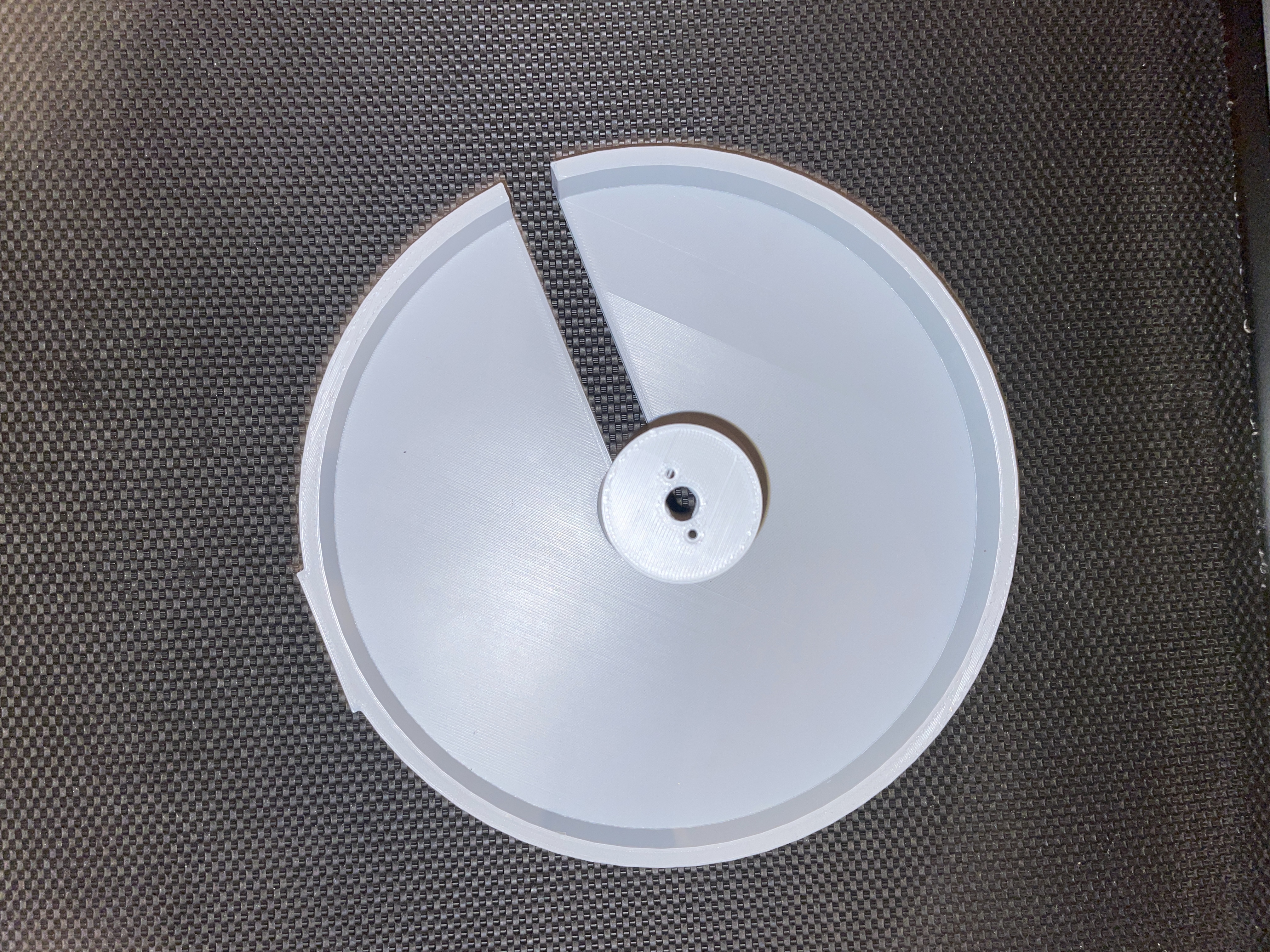
- Base
- Arm
- 12V DC Motor with Encoder
- Hriday
Issues
The obvious issue here is that the mechanism tips over, far from the maximum speed needed of the motor. This is because the base is not wide enough. This is easily addressable by making the base wider. Seems that all the FRC kids at this school can't get this right.
The motor-hole was very loose and can be made tighter